Layer 2 switches are frequently installed in the enterprise for high-speed connectivity between end stations at the data link layer. Layer 3 switches are a relatively new phenomenon, made popular by (among others) the trade press. This article details some of the issues in the evolution of Layer 2 and Layer 3 switches. We hypothesize that that the technology is evolutionary and has its origins in earlier products.
Bridging technology has been around since the 1980s (and maybe even earlier). Bridging involves segmentation of local-area networks (LANs) at the Layer 2 level. A multiport bridge typically learns about the Media Access Control (MAC) addresses on each of its ports and transparently passes MAC frames destined to those ports. These bridges also ensure that frames destined for MAC addresses that lie on the same port as the originating station are not forwarded to the other ports. For the sake of this discussion, we consider only Ethernet LANs.
Layer 2 switches effectively provide the same functionality. They are similar to multiport bridges in that they learn and forward frames on each port. The major difference is the involvement of hardware that ensures that multiple switching paths inside the switch can be active at the same time. For example, consider Figure 1, which details a four-port switch with stations A on port 1, B on port 2, C on port 3 and D on port 4. Assume that A desires to communicate with B, and C desires to communicate with D. In a single CPU bridge, this forwarding would typically be done in software, where the CPU would pick up frames from each of the ports sequentially and forward them to appropriate output ports. This process is highly inefficient in a scenario like the one indicated previously, where the traffic between A and B has no relation to the traffic between C and D.
Figure 1: Layer 2 switch with External Router for Inter-VLAN traffic and connecting to the Internet
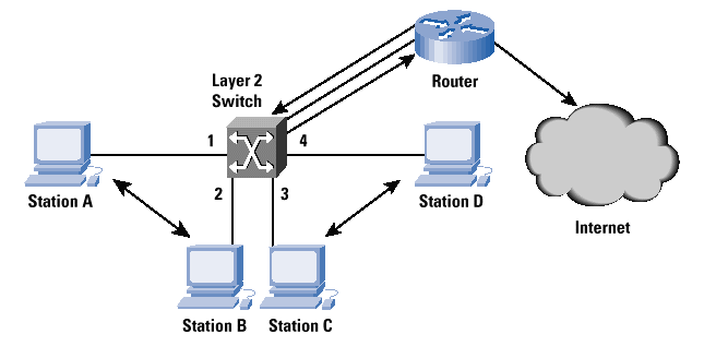
(Click on image to enlarge.)
Enter hardware-based Layer 2 switching. Layer 2 switches with their hardware support are able to forward such frames in parallel so that A and B and C and D can have simultaneous conversations. The parallel-ism has many advantages. Assume that A and B are NetBIOS stations, while C and D are Internet Protocol (IP) stations. There may be no rea-son for the communication between A and C and A and D. Layer 2 switching allows this coexistence without sacrificing efficiency.
In reality, however, LANs are rarely so clean. Assume a situation where A,B,C, and D are all IP stations. A and B belong to the same IP subnet, while C and D belong to a different subnet. Layer 2 switching is fine, as long as only A and B or C and D communicate. If A and C, which are on two different IP subnets, need to communicate, Layer 2 switching is inadequate?the communication requires an IP router. A corollary of this is that A and B and C and D belong to different broadcast domains?that is, A and B should not ?see? the MAC layer broadcasts from C and D, and vice versa. However, a Layer 2 switch cannot distinguish between these broadcasts?bridging technology involves forwarding broadcasts to all other ports, and it cannot tell when a broadcast is restricted to the same IP subnet.
Virtual LANs (VLANs) apply in this situation. In short, Layer 2 VLANs are Layer 2 broadcast domains. MAC broadcasts are restricted to the VLANs that stations are configured into. How can the Layer 2 switch make this distinction? By configuration. VLANs involve configuration of ports or MAC addresses. Port-based VLANs indicate that all frames that originate from a port belong to the same VLAN, while MAC address-based VLANs use MAC addresses to determine VLAN membership. In Figure 1, ports 1 and 2 belong to the same VLAN, while ports 3 and 4 belong to a different VLAN. Note that there is an implicit relationship between the VLANs and the IP subnets?however, configuration of Layer 2 VLANs does not involve specifying Layer 3 parameters.
We indicated earlier that stations on two different VLANs can com-municate only via a router. The router is typically connected to one of the switch ports (Figure 1). This router is sometimes referred to as a one-armed router since it receives and forwards traffic on to the same port. In reality, of course, such routers connect to other switches or to wide-area networks (WANs). Some Layer 2 switches provide this Layer 3 routing functionality within the same box to avoid an exter-nal router and to free another switch port. This scenario is reminiscent of the large multiprotocol routers of the early ?90s, which offered routing and bridging functions.
A popular classification of Layer 2 switches is ?cut-through? versus ?store-and-forward.? Cut-through switches make the forwarding decision as the frame is being received by just looking at the header of the frame. Store-and-forward switches receive the entire Layer 2 frame before making the forwarding decision. Hybrid adaptable switches which adapt from cut-through to store-and-forward based on the error rate in the MAC frames are very popular.
Layer 2 switches themselves act as IP end nodes for Simple Network Management Protocol (SNMP) management, Telnet, and Web based management. Such management functionality involves the presence of an IP stack on the router along with User Datagram Protocol (UDP), Transmission Control Protocol (TCP), Telnet, and SNMP functions. The switches themselves have a MAC address so that they can be addressed as a Layer 2 end node while also providing transparent switch functions. Layer 2 switching does not, in general, involve changing the MAC frame. However, there are situations when switches change the MAC frame. The IEEE 802.1Q Committee is working on a VLAN standard that involves ?tagging? a MAC frame with the VLAN it belongs to; this tagging process involves changing the MAC frame. Bridging technology also involves the Spanning-Tree Protocol. This is required in a multibridge network to avoid loops.
The same principles also apply towards Layer 2 switches, and most commercial Layer 2 switches support the Spanning-Tree Protocol. The previous discussion provides an outline of Layer 2 switching func-tions. Layer 2 switching is MAC frame based, does not involve altering the MAC frame, in general, and provides transparent switching in par-allel with MAC frames. Since these switches operate at Layer 2, they are protocol independent. However, Layer 2 switching does not scale well because of broadcasts. Although VLANs alleviate this problem to some extent, there is definitely a need for machines on different VLANs to communicate. One example is the situation where an orga-nization has multiple intranet servers on separate subnets (and hence VLANs), causing a lot of intersubnet traffic. In such cases, use of a router is unavoidable; Layer 3 switches enter at this point.
Layer 3 switching is a relatively new term, which has been ?extended? by a numerous vendors to describe their products. For example, one school uses this term to describe fast IP routing via hardware, while another school uses it to describe Multi Protocol Over ATM (MPOA). For the purpose of this discussion, Layer 3 switches are superfast rout-ers that do Layer 3 forwarding in hardware. In this article, we will mainly discuss Layer 3 switching in the context of fast IP routing, with a brief discussion of the other areas of application.
Consider the Layer 2 switching context shown in Figure 1. Layer 2 switches operate well when there is very little traffic between VLANs. Such VLAN traffic would entail a router?either ?hanging off? one of the ports as a one-armed router or present internally within the switch. To augment Layer 2 functionality, we need a router?which leads to loss of performance since routers are typically slower than switches. This scenario leads to the question: Why not implement a router in the switch itself, as discussed in the previous section, and do the forwarding in hardware?
Although this setup is possible, it has one limitation: Layer 2 switches need to operate only on the Ethernet MAC frame. This scenario in turn leads to a well-defined forwarding algorithm which can be implemented in hardware. The algorithm cannot be extended easily to Layer 3 protocols because there are multiple Layer 3 routable protocols such as IP, IPX, AppleTalk, and so on; and second, the forwarding decision in such protocols is typically more complicated than Layer 2 forwarding decisions.
What is the engineering compromise? Because IP is the most common among all Layer 3 protocols today, most of the Layer 3 switches today perform IP switching at the hardware level and forward the other protocols at Layer 2 (that is, bridge them). The second issue of complicated Layer 3 forwarding decisions is best illustrated by IP option processing, which typically causes the length of the IP header to vary, complicating the building of a hardware forwarding engine. However, a large number of IP packets do not include IP options?so, it may be overkill to design this processing into silicon. The compromise is that the most common (fast path) forwarding decision is designed into silicon, whereas the others are handled typically by a CPU on the Layer 3 switch.
To summarize, Layer 3 switches are routers with fast forwarding done via hardware. IP forwarding typically involves a route lookup, decrementing the Time To Live (TTL) count and recalculating the checksum, and forwarding the frame with the appropriate MAC header to the correct output port. Lookups can be done in hardware, as can the decrementing of the TTL and the recalculation of the checksum. The routers run routing protocols such as Open Shortest Path First (OSPF) or Routing Information Protocol (RIP) to communicate with other Layer 3 switches or routers and build their routing tables. These routing tables are looked up to determine the route for an incoming packet.
We have implicitly assumed that Layer 3 switches also provide Layer 2 switching functionality, but this assumption does not always hold true. Layer 3 switches can act like traditional routers hanging off multiple Layer 2 switches and provide inter-VLAN connectivity. In such cases, there is no Layer 2 functionality required in these switches. This concept can be illustrated by extending the topology in Figure 1?consider placing a pure Layer 3 switch between the Layer 2 Switch and the router. The Layer 3 Switch would off-load the router from inter-VLAN processing.
Figure 2: Combined Layer2/Layer3 Switch connecting directly to the Internet
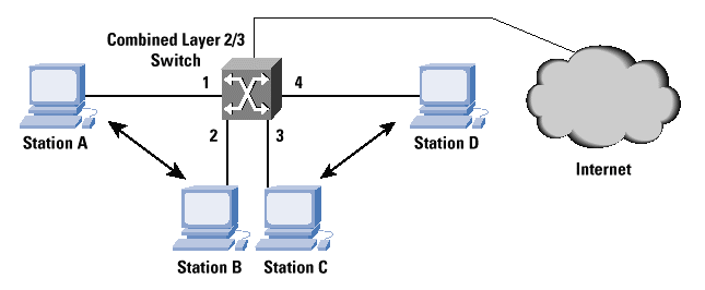
(Click on image to enlarge.)
Figure 2 illustrates the combined Layer 2/Layer 3 switching function-ality. The combined Layer 2/Layer 3 switch replaces the traditional router also. A and B belong to IP subnet 1, while C and D belong to IP subnet 2. Since the switch in consideration is a Layer 2 switch also, it switches traffic between A and B at Layer 2. Now consider the situ-ation when A wishes to communicate with C. A sends the IP packet addressed to the MAC address of the Layer 3 switch, but with an IP destination address equal to C?s IP address. The Layer 3 switch strips out the MAC header and switches the frame to C after performing the lookup, decrementing the TTL, recalculating the checksum and inserting C?s MAC address in the destination MAC address field. All of these steps are done in hardware at very high speeds.
Now how does the switch know that C?s IP destination address is Port 3? When it performs learning at Layer 2, it only knows C?s MAC address. There are multiple ways to solve this problem. The switch can perform an Address Resolution Protocol (ARP) lookup on all the IP subnet 2 ports for C?s MAC address and determine C?s IP-to-MAC mapping and the port on which C lies. The other method is for the switch to determine C?s IP-to-MAC mapping by snooping into the IP header on reception of a MAC frame.
Configuration of the Layer 3 switches is an important issue. When the Layer 3 switches also perform Layer 2 switching, they learn the MAC addresses on the ports?the only configuration required is the VLAN configuration. For Layer 3 switching, the switches can be configured with the ports corresponding to each of the subnets or they can perform IP address learning. This process involves snooping into the IP header of the MAC frames and determining the subnet on that port from the source IP address. When the Layer 3 switch acts like a one-armed router for a Layer 2 switch, the same port may consist of multiple IP subnets.
Management of the Layer 3 switches is typically done via SNMP. Layer 3 switches also have MAC addresses for their ports?this setup can be one per port, or all ports can use the same MAC address. The Layer 3 switches typically use this MAC address for SNMP, Telnet, and Web management communication.
Conceptually, the ATM Forum?s LAN Emulation (LANE) specificat-ion is closer to the Layer 2 switching model, while MPOA is closer to the Layer 3 switching model. Numerous Layer 2 switches are equipped with ATM interfaces and provide a LANE client function on that ATM interface. This scenario allows the bridging of MAC frames across an ATM network from switch to switch. The MPOA is closer to combined Layer2/Layer 3 switching, though the MPOA client does not have any routing protocols running on it. (Routing is left to the MPOA server under the Virtual Router model.)
Do Layer 3 switches completely eliminate need for the traditional router ? No, routers are still needed, especially where connections to the wide area are required. Layer 3 switches may still connect to such routers to learn their tables and route packets to them when these packets need to be sent over the WAN. The switches will be very effective on the workgroup and the backbone within an enterprise, but most likely will not replace the router at the edge of the WAN (read Internet in many cases). Routers perform numerous other functions like filtering with access lists, inter-Autonomous System (AS) routing with protocols such as the Border Gateway Protocol (BGP), and so on. Some Layer 3 switches may completely replace the need for a router if they can provide all these functions (see Figure 2).
[1]
Computer Networks, 3rd Edition, Andrew S. Tanenbaum, ISBN 0-13- 349945-6, Prentice-Hall, 1996.
[2]
Interconnections: Bridges and Routers, Radia Perlman, ISBN 0-201- 56332-0, Addison-Wesley, 1992.
[3] "MAC Bridges," ISO/IEC 10038, ANSI/IEEE Standard 802.1 D-1993.
[4] "Draft Standard for Virtual Bridged Local Area Networks," IEEE P802.1Q/D6, May 1997.
[5] "Internet Protocol," Jon Postel, RFC 791, 1981.
[6] "Requirements for IP Version 4 Routers," Fred Baker, RFC 1812, June 1995.
[7] "LAN Emulation over ATM Version 1.0," af-lane-0021.000, The ATM Forum, January 1995.
[8] "Multiprotocol over ATM (MPOA) Specication Version 1.0" af-mpoa-0087.000, The ATM Forum, July 1997

)
)